
The steam turbines in newly-built large and medium-sized units are all controlled by Digital Electrohydraulic Control System (DEH). Generally, in the trial operation stage of the newly-built unit, the steam turbine is under single-valve control and each high-pressure control valve of the steam turbine is involved in the adjustment at the same time, and the opening degree of each door is the same. When the load is low, the opening degree of the high-pressure adjustment door is small, so the high-pressure adjustment door has a large closure loss, which is not conducive to the long-term economic operation of the unit.
Therefore, after the trial production of the newly-built unit is completed, in order to improve the economy of the unit operation, it is a very important measure to switch the steam turbine from single valve operation to sequence valve operation. Although sequence valve control is a basic function in DEH, due to field installation and other factors, the actual flow characteristics of the high pressure control valve will be different from the preset flow characteristic curve in DEH (DEH preset value at the factory).
This problem will lead to large unit load disturbances during single-valve-sequence valve switching, and abnormal changes in the main operating parameters of the turbine, affecting the unit's safety. Therefore, before the sequence valve function is put into use, the actual flow characteristics of the high-pressure control valve shall be verified through the characteristic test, and the overlap between the high-pressure control doors shall be set so that the switching between the single valve and the sequential valve can be performed smoothly, and the switching process can be reduced. The impact on the important parameters of the steam turbine (such as vibration, tile temperature, etc.), to ensure the safe and stable operation of the unit.
1DEH sequence valve control principle Sequential valve control is a control function of the power control of the unit in the DEH. According to the switching sequence of the high-pressure control valve of the steam turbine, the flow command of the turbine is distributed to determine the flow of each high-pressure control door, and finally the opening of each high-pressure control door is determined. degree. These control strategies are generally included in the DEH valve management control function.
Yangzhou No. 2 Power Plant (Yanzhou No. 2 Plant) selected Westinghouse WDPFMOD III digital electro-hydraulic control system. During the operation of the sequence valve, the turbine flow command FDEM was subject to back pressure correction, proportional offset correction, GV flow correction, and GV. After the flow opening function is corrected, the opening command of each GV is generated. The control principle is shown in Figure 1.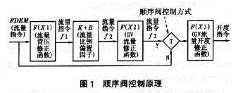
The FDEM can be manually specified or generated by the power conditioner operation during unit load control. The flow back pressure correction function F(X1) is a correction function of the unit flow demand and flow command. When steam turbines work at different flow rates, the steam turbine exhaust pressure changes, the steam enthalpy drops change, and the corresponding functional forces are different. Therefore, different steam flow commands need to be corrected. For example, as the load increases, the turbine steam flow increases, the steam turbine exhaust pressure increases, and the flow demand must be corrected to produce actual flow commands. Usually this is determined by the characteristics of the steam turbine itself. No trial setting is required. The flow ratio offset (K+B) and the GV flow rate correction function F(X2) determine the opening sequence, overlap degree, and flow rate command of the high pressure governor under the sequential valve control mode. The GV flow opening correction function F (X3) is the flow characteristic of the valve, which is the correspondence between the flow rate and the valve position and needs to be obtained through experiments.
2 Sequence valve characteristic test 2.1 Determination of test method Before the turbine is put into sequence valve control, it runs in single valve mode. As can be seen from FIG. 1, the flow rate command directly generates a valve position command through the GV flow opening correction function F(X3), which is independent of other functions, so it is possible to prioritize the GV flow opening correction function F(X3).
After the sequence valve is put into operation, the overlap degree of each valve can be actually verified, and the flow ratio bias factor (K 10 B) and the GV flow correction function F (X2) can be set. The back pressure correction function F(X1) is determined by the characteristics of the unit, so no setting is required.
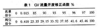
2.2GV flow opening correction function F (X3) characteristic test DEH works in the local mode, cutting off the power control loop, manual operation. Manually specify the flow command and measure the functional relationship between the flow command FDEM and the turbine steam flow. When No. 1 unit of No. 2 unit of Yangzhou Plant was tested, under the condition that the main steam pressure was constant (16.0MPa), the flow command was manually given to measure the steam flow at different load points. When the flow command does not have a linear relationship with the actual flow, the GV flow opening correction function can be modified until the requirement is satisfied. Through the test, the GV flow opening correction function F(X3) is obtained, as shown in Table 1.
 Under this GV flow opening correction function, the corresponding relationship between the flow command FDEM and the main steam flow is shown in Fig. 2. The flow command FDEM has a linear relationship with the main steam flow, and the linearity is good.
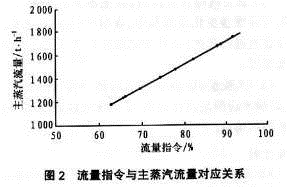
2.3 Back Pressure Correction Function F(X1)
The back pressure correction function F(X1) is provided by the turbine plant. The actual function setting of No. 1 unit in No. 2 Plant of Yang'e Second Plant is shown in Table 2.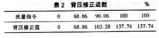
2.4 Flow Proportional Bias Factor (K+B) Setting Flow Proportional The bias factor (K+B) is determined based on the design flow of the valve and the sequence of opening of the valve when the valve is sequenced. When No. 1 steam turbine of No. 2 unit of No. 2 Plant operates in the sequence valve, GV3 and GV4 are turned on at the same time, and GV1 and GV2 are sequentially opened in consideration of the overlap between valves.
(1) Calculation of GV3, GV4 Flow Proportional Offset Factor (K+B) Since the GV3, GV4 valves are open at the same time, the flow ratio factor can be calculated simultaneously. According to the design data, when the GV3 and GV4 valve flow rate is 69% of the rated flow rate and the flow command FDEM is 69% (the flow rate command f1 corrected by the back pressure is 69%), the flow rate command of GV3 and GV4, f2 should be 100. %, GV3, GV4 open enough. When the flow rate command FDEM is 0% (flow rate command f1 after back pressure correction is 0%), the flow rate command of GV3 and GV4. F2 should be 0%, GV3, GV4 off. So it's calculated as follows:
0=K×0 ten B; 100=K×69+B
The flow ratio bias factors for GV3 and GV4 are:
K=1.45, B=0
(2) Calculation of GV1 flow ratio bias factor (K10B) Since GV1 is turned on after GV3 and GV4 valves, considering that steam turbine exhaust pressure increases with the increase of turbine steam flow, the valve flow of GV1 is 21% of the rated flow, and when the flow command FDEM is 69% (after the back pressure corrected flow command f1 is 69%), the GV1 flow command, f2 is 0%, GVl closed; when the flow command FDEM is 90% (The flow rate command f1 corrected by the back pressure is 103%), and the GV1 flow rate command is 100%, and the GV1 is opened. So it's calculated as follows:
0=K×69 ten B
100=K×103 Ten B
Get the flow ratio bias factor for GV1:
K=2.9, B=-200
(3) Calculation of GV2 flow rate proportional offset factor (K10B) Since GV2 is turned on after the GV1 valve, considering that the steam turbine exhaust pressure increases with the steam turbine flow rate, the GV1 valve flow rate is 10%. The rated flow rate, and when the flow rate command FDEM is 90% (the flow rate command f1 corrected by the back pressure is 103%), the flow rate command of the GV2. F2 is 0%, GV2 is closed; When the flow command FDEM is 100% (after the back pressure correction flow command f1 is 137%), the flow command f2 of GV2 is 100%, GV2 opens. So it's calculated as follows:
0=K×103+B
100=K×l37+B
Get the flow ratio bias factor for GV1:
K=2.9, B=-300
(4) The GV flow correction function F(X2) setting the GV flow correction function should be determined experimentally. Determine the GV flow correction function to determine the degree of overlap between the valves. The No. 1 unit of No. 2 unit of Yang’e No. 2 starts first and does not need to set the degree of overlap. The test found that when the flow command FDEM increased to 66.7%, GV3, GV4 open to 52.2%, the flow command FDEM and the actual steam flow has not been linear, then need to open GV1 to modify the relationship between flow command FDEM and the actual flow, Make it linear. After the flow command FDEM is increased to 69%, GV3/GV4 is opened. Therefore, there is a 2.3% overlap between GV1 and GV3/GV4, which should be set in the GV flow correction function F(X2) (-5,0). )at this point. Under rated conditions, when the flow command FDEM reaches 90%, the unit output has reached 600MW
(100% load), GV2 is off at this time. If the unit operating parameters are low, such as main steam pressure and main steam temperature are lower than the rated parameters, then when the flow command FDEM reaches 90%, GV3, GV4, GV1 will not be able to reach 600MW, and the flow command can Continue to increase to 100%. At this time, GV2 will be from the closed state to the fully open position. Since No. 1 unit of No. 2 Plant of Yang'e No. 2 was subjected to an overlap test at the rated condition, when the flow rate command was 90%, the output of the unit had reached a load of 600 MW, and the CV2 was still closed. Therefore, the degree of overlap between GV1 and GV2 was not set in the test.
If you need to set, the method is the same as above. The overlap function of each valve is set after the test is shown in Table 3.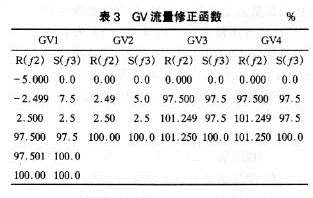 3 Test results When the No. 1 unit of No. 2 unit of Yang’e No. 1 plant was controlled by the sequence valve before the test, the switching process was not smooth, especially when the sequence valve was controlled, the No. 1 tile temperature rose rapidly, which affected the safety of the unit. After the sequence valve performance test, No. 1 tile temperature was effectively improved during the load change, and the tile temperature reached the maximum at the load section of about 480 MW. With the increase of the load, the tile temperature began to decrease and stabilized. During the sequence valve switching process, the load disturbance is small, there is no major change in the vibration and tile temperature of the turbine, and the sequence valve control function is normally input, and the economical operation of the unit is improved.
So far, No. 1 unit of No. 2 unit of Yangzhou No. 1 unit has been put into operation normally. When the single valve and sequence valve are switched, the unit runs stably, main steam temperature and main steam pressure are relatively stable, and all important operating parameters of the steam turbine are not abnormal.
The sequence of valve opening when the valve is in sequence is shown in Figure 3.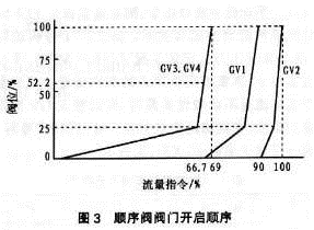
4 Test points (1) When verifying the valve flow characteristic curve, the main steam pressure and temperature should be kept constant in order to ensure the comparability of the steam flow rates of the turbines with different valve openings.
(2) When determining the degree of valve overlap, the flow rate command should be slowly changed in the vicinity of the load point where the valve is opened before and after, to obtain the overlap of the valve. The test should be repeated several times, taking the average of several tests as the overlap of the valve.
(3) Before the test, it should be determined that the dead zone and sluggish rate of each electro-hydraulic converter and oil motive should meet the design requirements, so as to ensure that the implementing agency does not affect the accuracy of the test.
Therefore, after the trial production of the newly-built unit is completed, in order to improve the economy of the unit operation, it is a very important measure to switch the steam turbine from single valve operation to sequence valve operation. Although sequence valve control is a basic function in DEH, due to field installation and other factors, the actual flow characteristics of the high pressure control valve will be different from the preset flow characteristic curve in DEH (DEH preset value at the factory).
This problem will lead to large unit load disturbances during single-valve-sequence valve switching, and abnormal changes in the main operating parameters of the turbine, affecting the unit's safety. Therefore, before the sequence valve function is put into use, the actual flow characteristics of the high-pressure control valve shall be verified through the characteristic test, and the overlap between the high-pressure control doors shall be set so that the switching between the single valve and the sequential valve can be performed smoothly, and the switching process can be reduced. The impact on the important parameters of the steam turbine (such as vibration, tile temperature, etc.), to ensure the safe and stable operation of the unit.
1DEH sequence valve control principle Sequential valve control is a control function of the power control of the unit in the DEH. According to the switching sequence of the high-pressure control valve of the steam turbine, the flow command of the turbine is distributed to determine the flow of each high-pressure control door, and finally the opening of each high-pressure control door is determined. degree. These control strategies are generally included in the DEH valve management control function.
Yangzhou No. 2 Power Plant (Yanzhou No. 2 Plant) selected Westinghouse WDPFMOD III digital electro-hydraulic control system. During the operation of the sequence valve, the turbine flow command FDEM was subject to back pressure correction, proportional offset correction, GV flow correction, and GV. After the flow opening function is corrected, the opening command of each GV is generated. The control principle is shown in Figure 1.
The FDEM can be manually specified or generated by the power conditioner operation during unit load control. The flow back pressure correction function F(X1) is a correction function of the unit flow demand and flow command. When steam turbines work at different flow rates, the steam turbine exhaust pressure changes, the steam enthalpy drops change, and the corresponding functional forces are different. Therefore, different steam flow commands need to be corrected. For example, as the load increases, the turbine steam flow increases, the steam turbine exhaust pressure increases, and the flow demand must be corrected to produce actual flow commands. Usually this is determined by the characteristics of the steam turbine itself. No trial setting is required. The flow ratio offset (K+B) and the GV flow rate correction function F(X2) determine the opening sequence, overlap degree, and flow rate command of the high pressure governor under the sequential valve control mode. The GV flow opening correction function F (X3) is the flow characteristic of the valve, which is the correspondence between the flow rate and the valve position and needs to be obtained through experiments.
2 Sequence valve characteristic test 2.1 Determination of test method Before the turbine is put into sequence valve control, it runs in single valve mode. As can be seen from FIG. 1, the flow rate command directly generates a valve position command through the GV flow opening correction function F(X3), which is independent of other functions, so it is possible to prioritize the GV flow opening correction function F(X3).
After the sequence valve is put into operation, the overlap degree of each valve can be actually verified, and the flow ratio bias factor (K 10 B) and the GV flow correction function F (X2) can be set. The back pressure correction function F(X1) is determined by the characteristics of the unit, so no setting is required.
2.2GV flow opening correction function F (X3) characteristic test DEH works in the local mode, cutting off the power control loop, manual operation. Manually specify the flow command and measure the functional relationship between the flow command FDEM and the turbine steam flow. When No. 1 unit of No. 2 unit of Yangzhou Plant was tested, under the condition that the main steam pressure was constant (16.0MPa), the flow command was manually given to measure the steam flow at different load points. When the flow command does not have a linear relationship with the actual flow, the GV flow opening correction function can be modified until the requirement is satisfied. Through the test, the GV flow opening correction function F(X3) is obtained, as shown in Table 1.
2.3 Back Pressure Correction Function F(X1)
The back pressure correction function F(X1) is provided by the turbine plant. The actual function setting of No. 1 unit in No. 2 Plant of Yang'e Second Plant is shown in Table 2.
2.4 Flow Proportional Bias Factor (K+B) Setting Flow Proportional The bias factor (K+B) is determined based on the design flow of the valve and the sequence of opening of the valve when the valve is sequenced. When No. 1 steam turbine of No. 2 unit of No. 2 Plant operates in the sequence valve, GV3 and GV4 are turned on at the same time, and GV1 and GV2 are sequentially opened in consideration of the overlap between valves.
(1) Calculation of GV3, GV4 Flow Proportional Offset Factor (K+B) Since the GV3, GV4 valves are open at the same time, the flow ratio factor can be calculated simultaneously. According to the design data, when the GV3 and GV4 valve flow rate is 69% of the rated flow rate and the flow command FDEM is 69% (the flow rate command f1 corrected by the back pressure is 69%), the flow rate command of GV3 and GV4, f2 should be 100. %, GV3, GV4 open enough. When the flow rate command FDEM is 0% (flow rate command f1 after back pressure correction is 0%), the flow rate command of GV3 and GV4. F2 should be 0%, GV3, GV4 off. So it's calculated as follows:
0=K×0 ten B; 100=K×69+B
The flow ratio bias factors for GV3 and GV4 are:
K=1.45, B=0
(2) Calculation of GV1 flow ratio bias factor (K10B) Since GV1 is turned on after GV3 and GV4 valves, considering that steam turbine exhaust pressure increases with the increase of turbine steam flow, the valve flow of GV1 is 21% of the rated flow, and when the flow command FDEM is 69% (after the back pressure corrected flow command f1 is 69%), the GV1 flow command, f2 is 0%, GVl closed; when the flow command FDEM is 90% (The flow rate command f1 corrected by the back pressure is 103%), and the GV1 flow rate command is 100%, and the GV1 is opened. So it's calculated as follows:
0=K×69 ten B
100=K×103 Ten B
Get the flow ratio bias factor for GV1:
K=2.9, B=-200
(3) Calculation of GV2 flow rate proportional offset factor (K10B) Since GV2 is turned on after the GV1 valve, considering that the steam turbine exhaust pressure increases with the steam turbine flow rate, the GV1 valve flow rate is 10%. The rated flow rate, and when the flow rate command FDEM is 90% (the flow rate command f1 corrected by the back pressure is 103%), the flow rate command of the GV2. F2 is 0%, GV2 is closed; When the flow command FDEM is 100% (after the back pressure correction flow command f1 is 137%), the flow command f2 of GV2 is 100%, GV2 opens. So it's calculated as follows:
0=K×103+B
100=K×l37+B
Get the flow ratio bias factor for GV1:
K=2.9, B=-300
(4) The GV flow correction function F(X2) setting the GV flow correction function should be determined experimentally. Determine the GV flow correction function to determine the degree of overlap between the valves. The No. 1 unit of No. 2 unit of Yang’e No. 2 starts first and does not need to set the degree of overlap. The test found that when the flow command FDEM increased to 66.7%, GV3, GV4 open to 52.2%, the flow command FDEM and the actual steam flow has not been linear, then need to open GV1 to modify the relationship between flow command FDEM and the actual flow, Make it linear. After the flow command FDEM is increased to 69%, GV3/GV4 is opened. Therefore, there is a 2.3% overlap between GV1 and GV3/GV4, which should be set in the GV flow correction function F(X2) (-5,0). )at this point. Under rated conditions, when the flow command FDEM reaches 90%, the unit output has reached 600MW
(100% load), GV2 is off at this time. If the unit operating parameters are low, such as main steam pressure and main steam temperature are lower than the rated parameters, then when the flow command FDEM reaches 90%, GV3, GV4, GV1 will not be able to reach 600MW, and the flow command can Continue to increase to 100%. At this time, GV2 will be from the closed state to the fully open position. Since No. 1 unit of No. 2 Plant of Yang'e No. 2 was subjected to an overlap test at the rated condition, when the flow rate command was 90%, the output of the unit had reached a load of 600 MW, and the CV2 was still closed. Therefore, the degree of overlap between GV1 and GV2 was not set in the test.
If you need to set, the method is the same as above. The overlap function of each valve is set after the test is shown in Table 3.
So far, No. 1 unit of No. 2 unit of Yangzhou No. 1 unit has been put into operation normally. When the single valve and sequence valve are switched, the unit runs stably, main steam temperature and main steam pressure are relatively stable, and all important operating parameters of the steam turbine are not abnormal.
The sequence of valve opening when the valve is in sequence is shown in Figure 3.
4 Test points (1) When verifying the valve flow characteristic curve, the main steam pressure and temperature should be kept constant in order to ensure the comparability of the steam flow rates of the turbines with different valve openings.
(2) When determining the degree of valve overlap, the flow rate command should be slowly changed in the vicinity of the load point where the valve is opened before and after, to obtain the overlap of the valve. The test should be repeated several times, taking the average of several tests as the overlap of the valve.
(3) Before the test, it should be determined that the dead zone and sluggish rate of each electro-hydraulic converter and oil motive should meet the design requirements, so as to ensure that the implementing agency does not affect the accuracy of the test.
Gun Nail,Air Gun Nail,Concrete Nail
Shandong Shanglong Economic and Trade Corporation Ltd , http://www.chthreadedrod.com