
Abstract: This paper first introduces the temperature rise limit of the motor, and then uses a combination of test data and principle analysis to explain the temperature rise of the motor under the power supply condition of the inverter, and then introduces the countermeasures to ease the temperature rise.
1. Introduction In order to save energy and improve process control, more and more industrial processes use frequency converters to increase the overall efficiency of the production system. The pwm pulse voltage output from the inverter is rich in harmonics, pulse frequency is high, and the rising edge is steep. This situation is very different from that of driving the motor with an AC sine wave of 50hz. During the energy conversion process, the interior of the motor will be unavoidable. Loss of ground causes the temperature of the motor to rise. When the temperature rises above the maximum allowable operating temperature, the service life of the motor will be greatly reduced. Therefore, it is very important to study the temperature rise of the motor and its mitigation measures. In addition, due to the complex motor structure and different heat dissipation conditions, the temperature distribution and temperature rise of the various parts of the motor are not exactly the same. However, there are currently few specific data available for reference.
2, the temperature rise of the motor limit Motor commonly used insulation materials, according to its heat resistance, is divided into a, e, b, f and h and other five. Class a insulation uses organic materials such as cotton yarn, silk, and paper that are impregnated or used in oil when immersed or used. Class E insulation is an insulation film made of polyester resin, epoxy resin, and triacetate, b, f, h The basic materials for insulation are mica, asbestos, and glass fiber, but the heat resistance of dipping lacquer is different. Table 1 lists the maximum allowable operating temperature for each level of insulation.
Table 1 The maximum allowable operating temperature for insulation at all levels
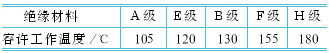
The above heat resistance means that it can be used at this temperature for a long period of time. When the operating temperature exceeds the maximum allowable operating temperature, the service life will be rapidly reduced. Tests have shown that for class a insulation, if it has been at 90 ~ 95 °C, the service life of up to 20 years; when the operating temperature is above 95 °C, the temperature increased by 8 °C, insulation life will be reduced by half (commonly known 8 °C theorem); for example, has been working at 110 °C, life is only 4 to 5 years.
Most of the general motor with e-class and b-class insulation. Motors that are required to be used in high temperature applications, such as crane and metallurgical motors, often use f- and h-class insulation.
The difference between the temperature of a certain part of the motor and the temperature of the surrounding cooling medium is called the temperature rise of the part and is generally represented by θ. When the insulating material used in this section is determined, the maximum permissible operating temperature of the component is determined, at which point the temperature rise limit depends on the temperature of the cooling medium. The higher the temperature of the cooling medium, the lower the allowable temperature rise.
Taking into account the large changes in the ambient temperature of various regions and seasons throughout the country, the national standard gb755-87 (motor basic technical requirements) clearly stipulates that, when the altitude is less than 1000m, the ambient air temperature is specified as 40°C, and the maximum ambient temperature is greater than 40°C. When δt0 is higher (δt0 does not exceed 20°C), the temperature rise limit should be reduced by δt0 accordingly; if it is lower than 40°C, the temperature rise limit is generally maintained at the original value. When the altitude is above 1000m, but not more than 4000m, the temperature rise limit is calibrated according to the difference in altitude between the test and the place of use.
After the electric motor is trial-produced, a temperature rise test shall be carried out to determine its actual temperature rise. Since the measurement results obtained by different measurement methods are different, the temperature measurement method should also be specified while specifying the temperature rise limit. There are three commonly used measurement methods: thermometer method, resistance method, and buried thermometer method. The maximum temperature allowed for the components specified in the national standard varies depending on the measurement method. For example, when the ambient air temperature is 40°C, the ac motor AC winding with a class b insulation below 5000kw is used. The temperature rise limit is defined as: resistance method -80°C; thermometer method -90°C; plus ambient temperature, Its value is lower than or equal to the allowable operating temperature of the b-grade material.
3. Temperature rise of motor during variable frequency power supply For the frequency converter power supply motor, due to the presence of higher harmonics, the following additional losses will occur within the motor:
(1) Stator and rotor additional copper losses due to higher harmonics;
(2) Stator additional iron loss due to higher harmonics;
(3) Additional stray losses due to higher harmonics;
(4) When the three-phase asynchronous motor is operated at high frequency, the skin effect causes the rotor resistance to increase, resulting in a significant increase in the copper loss of the slip.
The additional losses caused by these higher harmonic voltages and currents cause the motor temperature rise to increase.
On the other hand, for an ordinary standard motor, the cooling fan is directly mounted on the rotor shaft, and the cooling effect of the motor at the low frequency operation is greatly reduced, and the temperature rise of the motor is also increased. The relationship between the temperature rise of the motor and the cooling effect of the cooling air volume is:
In the formula, q is the cooling air volume, and n is the motor rotation speed. If the loss caused by the motor does not change, the temperature rise is inversely proportional to the 0.4 to 0.5 power of the rotation speed.
In short, when the motor, especially the ordinary motor, is powered by a frequency converter, the temperature rise of the motor will increase due to heat and heat dissipation. The increase in the temperature rise of the motor affects the service life of the windings, limits the output of the motor, and even severely burns the motor.
The experimental results of actually measuring the temperature rise are very useful for understanding the temperature distribution law of the motor, especially the influence of the variable frequency power supply on the temperature rise of the motor. A three-phase 4-pole 230v, 2.2kw cage induction motor was used as the experimental object, using a typical spwm inverter (running at 50hz) and power frequency sinusoidal power supply to compare the temperature rise of the motor. Using specialized design and manufacturing methods, 20 thermistor sensors (with stable performance and high precision) are placed or embedded in the motor body (stator, rotor, air gap, housing), with three sensors placed in the rotor. The stator end winding sensor is located at the radial center position of the stator winding (position 1, position 10). Generally, the temperature average of the two sensors of the shaft extension end and the fan end is taken as the final temperature. The temperature sensor layout is shown in Figure 1.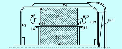
Sensor installation position description:
Rotor: 13 (axis center), 14 (axis extension side surface), 15 (fan side surface);
Stator winding end: 1 (axis extension side), 10 (fan side);
Stator core slot: 17 (axis extension side), 4 (fan side);
Airspace in the shell: 8 (shaft extension side), 19 (shaft extension side close to the stator winding), 20 (fan side); motor housing: 6.
In the case of power frequency sine and variable frequency power supplies, a large amount of data is measured at each temperature point, and the temperature curve at that point is obtained by the least squares method.
Fig. 2 shows the temperature curve corresponding to each measurement point when the frequency converter and the sinusoidal power supply respectively supply power under full load conditions. Figure 3 shows the temperature curve of the power supply motor of the inverter under different load conditions (the operating frequency is 50hz). Figure 4 shows the temperature curve under different load conditions when the sine wave is powered.
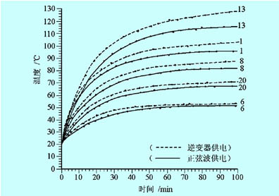
Obviously, the temperature curve has the same upward trend under the conditions of inverter and sinusoidal power supply. The additional temperature rise caused by the harmonics of the frequency converter is greater, the stator side is around 7°C (position 1) and the rotor side is about 15°C (position 13). The above results are also applicable to induction motors of other capacities similar in construction materials. In addition, the temperature distribution of the various parts of the motor is very different, the stator end winding (position 1) temperature is lower than the stator center (position 17) temperature, because the stator end winding cooling conditions are better; at the same time due to the cooling effect of the fan, The temperatures of the stator side winding (position 10) on the fan side and the air gap (position 20) in the housing are lower than the temperature of the stator end winding (position 1) on the corresponding shaft extension side and the air gap (position 8) in the housing. . Due to the complexity of heat transfer and the inconsistent cooling conditions, the relationship between temperature and loss is nonlinear.
For a squared torque load, the load torque at low speed operation decreases, and the copper consumption and heat generation of the motor decrease. Although the cooling capacity decreases at low speeds (for example, self-cooling or self-fan cooling), the temperature rise of the motor increases. Not too much. For a constant torque load, the load torque at the low speed operation does not change, the copper consumption and heat generation of the motor is not lower than that at high speed, and the cooling capacity at low speed is reduced, so the temperature rise of the motor will be greatly increased. Large, pay special attention when using it.
Table 2 shows the actual measured data of the temperature rise of the y100i2-4 self-fan cooling motor under the power supply condition of the inverter.
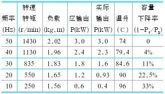
From the above table, it can be seen that although the torque and output power of the motor decrease with the decrease of the frequency (ie, the amount of heat generation), the temperature of the motor increases, especially when the motor runs at 30hz. The following temperature rise was particularly serious. Therefore, it can be seen that it is almost inevitable that the temperature rise of the motor after frequency conversion operation is unavoidable, especially when the ordinary motor is running at a low speed, the overheating phenomenon easily occurs. For this reason, it is very important to understand how the temperature rise of the motor is relieved.
4. Countermeasures for easing motor temperature rise Temperature rise is a key factor affecting the service life of the motor. The “8°C theorem†for the temperature rise of the motor is the proof of this view. As mentioned before, the temperature rise of the motor when the inverter is powered will be significantly higher than that of the industrial frequency power supply. In general, the lower the operating frequency of the motor, the higher the temperature rises. It is necessary to take effective measures to limit or ease the increase in the temperature rise of the motor and ensure the safe operation of the equipment.
Under the condition that the motor is selected, there are two aspects to limit or mitigate the temperature rise of the motor. One is to reduce the loss reasonably, that is, to reduce the heat generation; the other is to improve the cooling conditions so that the heat energy can be effectively emitted.
One of the fundamental measures to reduce the loss is to suppress harmonics, and the second is to limit the load torque. The specific measures are as follows:
(1) Take various measures to suppress harmonics, such as installing a filter on the output side of the inverter to improve the output harmonic performance and reduce the additional loss due to higher harmonics.
(2) Reasonably adjust the "carrier frequency" parameter to improve the harmonic performance and reduce various losses of the motor. It is generally considered that the carrier frequency is moderately increased, the higher harmonic content will be reduced, and the motor loss will be small. However, it must be noted that excessively high carrier frequency will aggravate the impact voltage of the motor and adversely affect the insulation of the motor, and the loss of the inverter itself must be increased. Therefore, the setting of the carrier frequency should not be too high.
(3) Moderately reduce the output voltage of the inverter, ie, reduce the u/f reference for situations of load shedding or light-load operation of the motor.
(4) For the occasion of load reduction, the maximum operating frequency limit should be properly reduced to reduce the motor output.
(5) Properly increase the capacity of the motor and frequency converter and reduce its load factor.
In addition, if the production process allows, the motor light load is also a simple and effective method.
FIG. 5 shows an example of the continuous operating torque and the short-term maximum torque characteristics that the motor allows when the variable-frequency power supply (a combination of inverter capacity and motor capacity is 1:1). These characteristics differ depending on the type and structure of the motor. The details need to be studied based on the data provided by the manufacturers.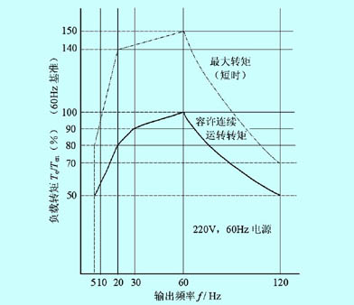
In FIG. 5 , the allowable continuous operation torque indicates the allowable torque value that can limit the motor temperature rise within a predetermined value when the universal motor is continuously operated. If the 220V, 60hz power supply is used to operate the motor continuously at 20hz, if the load torque is within 80% of the rated value of the motor, the temperature rise of the motor will not exceed the specified value. The maximum torque represents the maximum torque that the motor can generate when it is driven by a universal motor. Since this torque value cannot be continuously operated, it is a short-term rating.
Specific measures for improving heat dissipation:
(1) Select variable frequency motor or forced air motor.
(2) Transform the original equipment and set up a special cooling fan.
In addition, if the production process allows, limiting the minimum frequency of motor operation, and ensuring the cooling capacity of the fan-cooled motor at low speed, is also a simple and effective method.
It is worth pointing out that the current large-scale use of ordinary small and medium AC motors are designed according to constant frequency / constant voltage (50hz/380v), in order to reduce the cost of these motors are self-contained fan-type cooling, cooling air volume is basically based on the motor If the rated speed is designed, the cooling capacity of the fan-cooled motor will be reduced after the motor speed regulation (speed reduction) is seldom considered. In today's widespread use of frequency converters, such motors have in fact been unable to adapt to the requirements of variable frequency speed control, variable frequency motor is one of the ideal choice. Compared with ordinary AC motors, inverter motors are currently expensive and many companies cannot afford them. To reform the cooling method of small and medium-sized motors, that is, to use his fan-cooled cooling method, which has been used in large-scale motors in the past, is a simple, effective and inexpensive solution.
When using a general-purpose inverter to reconstruct the constant speed system of the old common asynchronous machine, the following points should be especially noted. For a squared torque load (such as fans, pumps) generally directly select the appropriate frequency converter; but for constant torque load should pay attention to the measured or estimated motor long-term operation frequency, identify the actual motor power consumption and motor margin. For motors with wider speed range, especially for motors with constant torque speed and constant power speed, self-fan-cooled motors cannot be used. This is unfavorable for high speed and low speed, and low speed cooling. The effect is poor, and excess cooling capacity at high speeds degrades the efficiency of the system.
5. Concluding remarks This article has studied the temperature rise of the induction motor under the condition of the power supply of the inverter, analyzed the cause of the increase of the motor temperature rise caused by the loss and heat dissipation of the motor, and explained the temperature distribution law of the motor through the test data. With the influence of the frequency conversion power supply on the temperature rise of the motor, specific measures for reducing the loss and improving the heat dissipation are proposed, which provide a reference for solving the problem of temperature rise of the motor.
1. Introduction In order to save energy and improve process control, more and more industrial processes use frequency converters to increase the overall efficiency of the production system. The pwm pulse voltage output from the inverter is rich in harmonics, pulse frequency is high, and the rising edge is steep. This situation is very different from that of driving the motor with an AC sine wave of 50hz. During the energy conversion process, the interior of the motor will be unavoidable. Loss of ground causes the temperature of the motor to rise. When the temperature rises above the maximum allowable operating temperature, the service life of the motor will be greatly reduced. Therefore, it is very important to study the temperature rise of the motor and its mitigation measures. In addition, due to the complex motor structure and different heat dissipation conditions, the temperature distribution and temperature rise of the various parts of the motor are not exactly the same. However, there are currently few specific data available for reference.
2, the temperature rise of the motor limit Motor commonly used insulation materials, according to its heat resistance, is divided into a, e, b, f and h and other five. Class a insulation uses organic materials such as cotton yarn, silk, and paper that are impregnated or used in oil when immersed or used. Class E insulation is an insulation film made of polyester resin, epoxy resin, and triacetate, b, f, h The basic materials for insulation are mica, asbestos, and glass fiber, but the heat resistance of dipping lacquer is different. Table 1 lists the maximum allowable operating temperature for each level of insulation.
Table 1 The maximum allowable operating temperature for insulation at all levels
The above heat resistance means that it can be used at this temperature for a long period of time. When the operating temperature exceeds the maximum allowable operating temperature, the service life will be rapidly reduced. Tests have shown that for class a insulation, if it has been at 90 ~ 95 °C, the service life of up to 20 years; when the operating temperature is above 95 °C, the temperature increased by 8 °C, insulation life will be reduced by half (commonly known 8 °C theorem); for example, has been working at 110 °C, life is only 4 to 5 years.
Most of the general motor with e-class and b-class insulation. Motors that are required to be used in high temperature applications, such as crane and metallurgical motors, often use f- and h-class insulation.
The difference between the temperature of a certain part of the motor and the temperature of the surrounding cooling medium is called the temperature rise of the part and is generally represented by θ. When the insulating material used in this section is determined, the maximum permissible operating temperature of the component is determined, at which point the temperature rise limit depends on the temperature of the cooling medium. The higher the temperature of the cooling medium, the lower the allowable temperature rise.
Taking into account the large changes in the ambient temperature of various regions and seasons throughout the country, the national standard gb755-87 (motor basic technical requirements) clearly stipulates that, when the altitude is less than 1000m, the ambient air temperature is specified as 40°C, and the maximum ambient temperature is greater than 40°C. When δt0 is higher (δt0 does not exceed 20°C), the temperature rise limit should be reduced by δt0 accordingly; if it is lower than 40°C, the temperature rise limit is generally maintained at the original value. When the altitude is above 1000m, but not more than 4000m, the temperature rise limit is calibrated according to the difference in altitude between the test and the place of use.
After the electric motor is trial-produced, a temperature rise test shall be carried out to determine its actual temperature rise. Since the measurement results obtained by different measurement methods are different, the temperature measurement method should also be specified while specifying the temperature rise limit. There are three commonly used measurement methods: thermometer method, resistance method, and buried thermometer method. The maximum temperature allowed for the components specified in the national standard varies depending on the measurement method. For example, when the ambient air temperature is 40°C, the ac motor AC winding with a class b insulation below 5000kw is used. The temperature rise limit is defined as: resistance method -80°C; thermometer method -90°C; plus ambient temperature, Its value is lower than or equal to the allowable operating temperature of the b-grade material.
3. Temperature rise of motor during variable frequency power supply For the frequency converter power supply motor, due to the presence of higher harmonics, the following additional losses will occur within the motor:
(1) Stator and rotor additional copper losses due to higher harmonics;
(2) Stator additional iron loss due to higher harmonics;
(3) Additional stray losses due to higher harmonics;
(4) When the three-phase asynchronous motor is operated at high frequency, the skin effect causes the rotor resistance to increase, resulting in a significant increase in the copper loss of the slip.
The additional losses caused by these higher harmonic voltages and currents cause the motor temperature rise to increase.
On the other hand, for an ordinary standard motor, the cooling fan is directly mounted on the rotor shaft, and the cooling effect of the motor at the low frequency operation is greatly reduced, and the temperature rise of the motor is also increased. The relationship between the temperature rise of the motor and the cooling effect of the cooling air volume is:
In the formula, q is the cooling air volume, and n is the motor rotation speed. If the loss caused by the motor does not change, the temperature rise is inversely proportional to the 0.4 to 0.5 power of the rotation speed.
In short, when the motor, especially the ordinary motor, is powered by a frequency converter, the temperature rise of the motor will increase due to heat and heat dissipation. The increase in the temperature rise of the motor affects the service life of the windings, limits the output of the motor, and even severely burns the motor.
The experimental results of actually measuring the temperature rise are very useful for understanding the temperature distribution law of the motor, especially the influence of the variable frequency power supply on the temperature rise of the motor. A three-phase 4-pole 230v, 2.2kw cage induction motor was used as the experimental object, using a typical spwm inverter (running at 50hz) and power frequency sinusoidal power supply to compare the temperature rise of the motor. Using specialized design and manufacturing methods, 20 thermistor sensors (with stable performance and high precision) are placed or embedded in the motor body (stator, rotor, air gap, housing), with three sensors placed in the rotor. The stator end winding sensor is located at the radial center position of the stator winding (position 1, position 10). Generally, the temperature average of the two sensors of the shaft extension end and the fan end is taken as the final temperature. The temperature sensor layout is shown in Figure 1.
Figure 1 temperature sensor distribution map
Sensor installation position description:
Rotor: 13 (axis center), 14 (axis extension side surface), 15 (fan side surface);
Stator winding end: 1 (axis extension side), 10 (fan side);
Stator core slot: 17 (axis extension side), 4 (fan side);
Airspace in the shell: 8 (shaft extension side), 19 (shaft extension side close to the stator winding), 20 (fan side); motor housing: 6.
In the case of power frequency sine and variable frequency power supplies, a large amount of data is measured at each temperature point, and the temperature curve at that point is obtained by the least squares method.
Fig. 2 shows the temperature curve corresponding to each measurement point when the frequency converter and the sinusoidal power supply respectively supply power under full load conditions. Figure 3 shows the temperature curve of the power supply motor of the inverter under different load conditions (the operating frequency is 50hz). Figure 4 shows the temperature curve under different load conditions when the sine wave is powered.
Figure 2 Temperature curve at full load
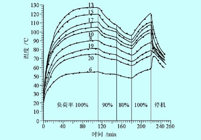
Fig. 3 Temperature curve under different load conditions
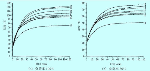
Figure 4 Temperature curve under different load conditions with sinusoidal power supply
Obviously, the temperature curve has the same upward trend under the conditions of inverter and sinusoidal power supply. The additional temperature rise caused by the harmonics of the frequency converter is greater, the stator side is around 7°C (position 1) and the rotor side is about 15°C (position 13). The above results are also applicable to induction motors of other capacities similar in construction materials. In addition, the temperature distribution of the various parts of the motor is very different, the stator end winding (position 1) temperature is lower than the stator center (position 17) temperature, because the stator end winding cooling conditions are better; at the same time due to the cooling effect of the fan, The temperatures of the stator side winding (position 10) on the fan side and the air gap (position 20) in the housing are lower than the temperature of the stator end winding (position 1) on the corresponding shaft extension side and the air gap (position 8) in the housing. . Due to the complexity of heat transfer and the inconsistent cooling conditions, the relationship between temperature and loss is nonlinear.
For a squared torque load, the load torque at low speed operation decreases, and the copper consumption and heat generation of the motor decrease. Although the cooling capacity decreases at low speeds (for example, self-cooling or self-fan cooling), the temperature rise of the motor increases. Not too much. For a constant torque load, the load torque at the low speed operation does not change, the copper consumption and heat generation of the motor is not lower than that at high speed, and the cooling capacity at low speed is reduced, so the temperature rise of the motor will be greatly increased. Large, pay special attention when using it.
Table 2 shows the actual measured data of the temperature rise of the y100i2-4 self-fan cooling motor under the power supply condition of the inverter.
Table 2 The influence of the rotation speed of the fan-cooled motor on the temperature rise.
From the above table, it can be seen that although the torque and output power of the motor decrease with the decrease of the frequency (ie, the amount of heat generation), the temperature of the motor increases, especially when the motor runs at 30hz. The following temperature rise was particularly serious. Therefore, it can be seen that it is almost inevitable that the temperature rise of the motor after frequency conversion operation is unavoidable, especially when the ordinary motor is running at a low speed, the overheating phenomenon easily occurs. For this reason, it is very important to understand how the temperature rise of the motor is relieved.
4. Countermeasures for easing motor temperature rise Temperature rise is a key factor affecting the service life of the motor. The “8°C theorem†for the temperature rise of the motor is the proof of this view. As mentioned before, the temperature rise of the motor when the inverter is powered will be significantly higher than that of the industrial frequency power supply. In general, the lower the operating frequency of the motor, the higher the temperature rises. It is necessary to take effective measures to limit or ease the increase in the temperature rise of the motor and ensure the safe operation of the equipment.
Under the condition that the motor is selected, there are two aspects to limit or mitigate the temperature rise of the motor. One is to reduce the loss reasonably, that is, to reduce the heat generation; the other is to improve the cooling conditions so that the heat energy can be effectively emitted.
One of the fundamental measures to reduce the loss is to suppress harmonics, and the second is to limit the load torque. The specific measures are as follows:
(1) Take various measures to suppress harmonics, such as installing a filter on the output side of the inverter to improve the output harmonic performance and reduce the additional loss due to higher harmonics.
(2) Reasonably adjust the "carrier frequency" parameter to improve the harmonic performance and reduce various losses of the motor. It is generally considered that the carrier frequency is moderately increased, the higher harmonic content will be reduced, and the motor loss will be small. However, it must be noted that excessively high carrier frequency will aggravate the impact voltage of the motor and adversely affect the insulation of the motor, and the loss of the inverter itself must be increased. Therefore, the setting of the carrier frequency should not be too high.
(3) Moderately reduce the output voltage of the inverter, ie, reduce the u/f reference for situations of load shedding or light-load operation of the motor.
(4) For the occasion of load reduction, the maximum operating frequency limit should be properly reduced to reduce the motor output.
(5) Properly increase the capacity of the motor and frequency converter and reduce its load factor.
In addition, if the production process allows, the motor light load is also a simple and effective method.
FIG. 5 shows an example of the continuous operating torque and the short-term maximum torque characteristics that the motor allows when the variable-frequency power supply (a combination of inverter capacity and motor capacity is 1:1). These characteristics differ depending on the type and structure of the motor. The details need to be studied based on the data provided by the manufacturers.
Figure 5 allows continuous running torque and maximum torque
In FIG. 5 , the allowable continuous operation torque indicates the allowable torque value that can limit the motor temperature rise within a predetermined value when the universal motor is continuously operated. If the 220V, 60hz power supply is used to operate the motor continuously at 20hz, if the load torque is within 80% of the rated value of the motor, the temperature rise of the motor will not exceed the specified value. The maximum torque represents the maximum torque that the motor can generate when it is driven by a universal motor. Since this torque value cannot be continuously operated, it is a short-term rating.
Specific measures for improving heat dissipation:
(1) Select variable frequency motor or forced air motor.
(2) Transform the original equipment and set up a special cooling fan.
In addition, if the production process allows, limiting the minimum frequency of motor operation, and ensuring the cooling capacity of the fan-cooled motor at low speed, is also a simple and effective method.
It is worth pointing out that the current large-scale use of ordinary small and medium AC motors are designed according to constant frequency / constant voltage (50hz/380v), in order to reduce the cost of these motors are self-contained fan-type cooling, cooling air volume is basically based on the motor If the rated speed is designed, the cooling capacity of the fan-cooled motor will be reduced after the motor speed regulation (speed reduction) is seldom considered. In today's widespread use of frequency converters, such motors have in fact been unable to adapt to the requirements of variable frequency speed control, variable frequency motor is one of the ideal choice. Compared with ordinary AC motors, inverter motors are currently expensive and many companies cannot afford them. To reform the cooling method of small and medium-sized motors, that is, to use his fan-cooled cooling method, which has been used in large-scale motors in the past, is a simple, effective and inexpensive solution.
When using a general-purpose inverter to reconstruct the constant speed system of the old common asynchronous machine, the following points should be especially noted. For a squared torque load (such as fans, pumps) generally directly select the appropriate frequency converter; but for constant torque load should pay attention to the measured or estimated motor long-term operation frequency, identify the actual motor power consumption and motor margin. For motors with wider speed range, especially for motors with constant torque speed and constant power speed, self-fan-cooled motors cannot be used. This is unfavorable for high speed and low speed, and low speed cooling. The effect is poor, and excess cooling capacity at high speeds degrades the efficiency of the system.
5. Concluding remarks This article has studied the temperature rise of the induction motor under the condition of the power supply of the inverter, analyzed the cause of the increase of the motor temperature rise caused by the loss and heat dissipation of the motor, and explained the temperature distribution law of the motor through the test data. With the influence of the frequency conversion power supply on the temperature rise of the motor, specific measures for reducing the loss and improving the heat dissipation are proposed, which provide a reference for solving the problem of temperature rise of the motor.
Features of concrete batching plant:It is assembled by building blocks, which is short, quick and convenient.It is convenient and quick to use the cylinder discharge or electric push rod to discharge.A variety of mixing processes, highly automated, high production efficiency,
Environmental protection and energy saving, using pulse dust removal, recycling waste-water for reuse.
Rcc Concrete Batching Plants,Fully Automatic Concrete Mixing Plant,Automatic Concrete Mixing Plant,Construction Concrete Mixing Plant
Shandong Zeyu Heavy Industry Science and Technology Co.,Ltd. , https://www.sdmobileconcretebatchingplant.com